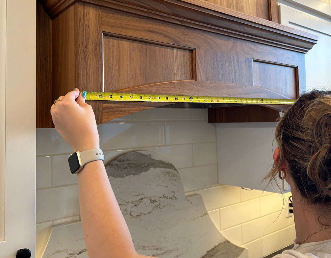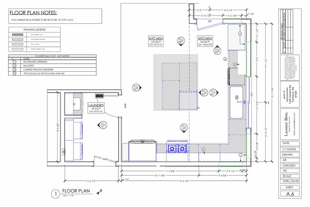
Construction blueprints, more commonly called construction drawings or plan sets today, are the coordinated instructions used to permit, price, and build a remodel. They document the existing home, proposed changes, dimensions, materials, structural requirements, and locations of systems such as lighting, plumbing, and ventilation.
Learning how to read construction blueprints does not mean becoming an architect or builder. As a homeowner, your job is to confirm that the drawings reflect the design you approved and the way you expect the finished space to work. Your design and construction teams remain responsible for technical accuracy, code compliance, and execution.
At Lamont Bros. Design & Construction, we use construction drawings to carry decisions from design into the field. Our designers create the plans, and our construction team reviews and builds from the same coordinated set. This helps preserve the design while giving everyone a shared reference for dimensions, materials, locations, and installation details.
The examples in this article come from real Lamont Bros. plan sets. Drawing organization and symbols vary among design firms, but the reading method remains largely the same.
Are Blueprints and Construction Drawings the Same Thing?
Homeowners commonly use “blueprints” to describe the plans for a construction project. The term originally referred to an older printing method that produced white lines on blue paper.
Most plans are now created and shared digitally. Professionals usually call them construction drawings, construction documents, plans, or a plan set. For a residential remodel, these terms often refer to the coordinated collection of drawings used to communicate what will be built.
A floor plan is only one part of that collection. A complete plan set may include:
- A cover sheet and sheet index
- Existing-condition and demolition plans
- Proposed floor plans
- Site and roof plans
- Exterior and interior elevations
- Building sections and construction details
- Structural drawings
- Finish, door, window, cabinet, and equipment schedules
- Plumbing, electrical, and mechanical drawings
Not every remodel requires every sheet. A bathroom update will generally need fewer drawings than an addition or whole-home remodel.
How to Read Construction Blueprints Step by Step
Do not begin by studying one room in isolation. Start by orienting yourself to the entire plan set.
First, confirm that you have the latest version. Then review the sheet index, title block, legend, and drawing scale. After that, compare the existing and demolition plans with the proposed floor plan. Follow the reference markers from the plans to the elevations, sections, and details. Finish by checking schedules, finishes, cabinetry, and mechanical, electrical, and plumbing information.
This order helps you move from the general scope of the project to the specific details used during construction.
Step 1: Confirm the Project and Revision
Before reading the design itself, check the title block.
The title block is usually located along the bottom or right side of each sheet. It identifies the project and helps you confirm that you are reviewing the correct drawing.
A title block commonly includes the project address, drawing title, sheet number, scale, issue date, and revision information. It may also identify the designer, architect, engineer, or other professionals responsible for the sheet.
Pay particular attention to the date and revision number. Construction drawings change as the design develops, permits are reviewed, and field conditions are resolved. Reviewing an outdated sheet can create confusion about which layout or detail has been approved.
If you receive revised drawings, ask your project team which issue is current and how previous versions should be handled.
Step 2: Review the Sheet Index and Drawing Numbers
The sheet index acts as the table of contents for the plan set.
It lists each sheet by number and title. Architectural sheets may begin with an “A,” structural sheets with an “S,” electrical sheets with an “E,” mechanical sheets with an “M,” and plumbing sheets with a “P.” These conventions vary, so use the index in your own set rather than assuming every firm follows the same system.
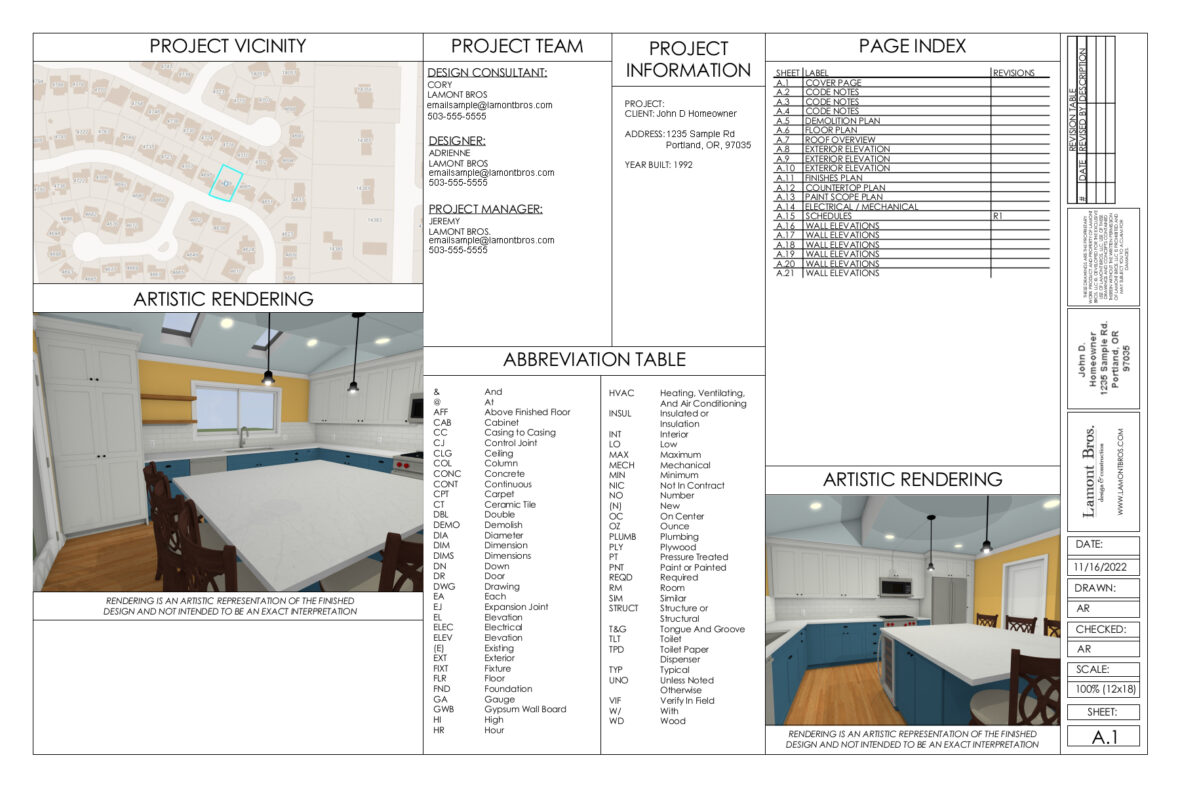
The sheet index helps you see which information is included and where to find it. It can also reveal that a detail shown on one page is explained more fully somewhere else.
If a floor-plan note refers to another sheet, do not stop at the note. Follow the reference to see the complete elevation, section, or construction detail.
Step 3: Read the Legend, Abbreviations, and General Notes
Construction drawings use symbols and abbreviations to communicate a large amount of information in limited space.
The legend identifies the symbols, line types, patterns, and abbreviations used in that plan set. A dashed line may represent an object above the cut plane, a hidden element, or something scheduled for removal. Its meaning depends on the drawing and legend.
General notes establish instructions that apply to several sheets or the full project. They may address dimensions, materials, code requirements, installation standards, or coordination among trades.
Read the project’s legend and notes before interpreting unfamiliar symbols. Construction conventions are common, but they are not perfectly universal.
Numbered Notes and Callouts
Some plan sets use numbered notes. A number on the drawing corresponds to a description in a nearby list. Check off each note as you locate the related element.
Other sets place text callouts directly beside the item being described. For a room with many callouts, begin at one corner and move around the space in a consistent direction.
Both methods require you to connect the note with the correct wall, fixture, cabinet, or building component. Reading the note without locating its reference on the drawing can lead to the wrong conclusion.
Step 4: Check the Drawing Scale and Dimensions
Construction drawings represent full-size buildings on much smaller sheets. The drawing scale establishes that relationship.
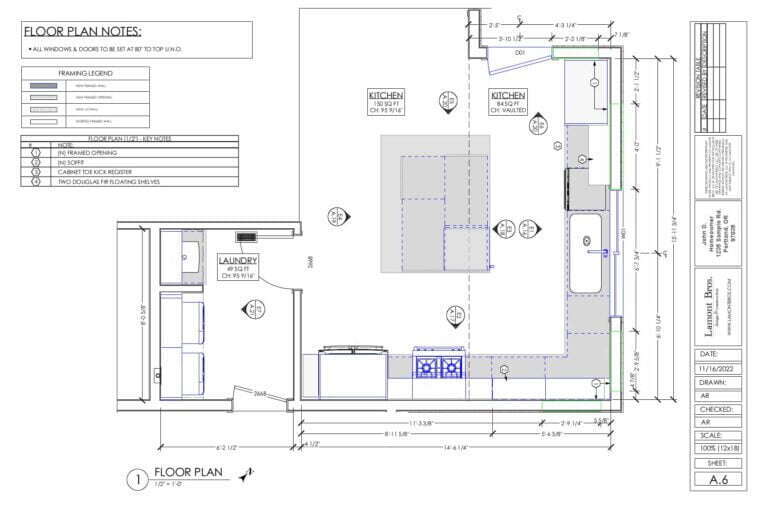
A floor plan might use a scale of 1/4 inch equals 1 foot. A site plan might use 1 inch equals 10 feet. A detailed cabinet or wall section may use a larger scale so smaller components can be shown clearly.
The scale should appear in the title block or near the drawing title.
Use written dimensions as your primary reference. Do not measure a printed or digital drawing unless the plan specifically permits it and you have confirmed that the sheet was printed or displayed at the intended size. Printing, scanning, and resizing can change the apparent scale.
If two dimensions appear to conflict, ask the designer or project manager for clarification. Do not choose the measurement that seems most likely.
Step 5: Compare Existing, Demolition, and Proposed Plans
A remodel plan set often shows the home in three conditions:
- What exists now
- What will be removed
- What will be built
Reviewing those drawings together is one of the fastest ways to see how the home will change.
Existing-Condition Plan
The existing-condition plan documents the layout before construction. It provides the baseline for the demolition and proposed plans.
Look for walls, doors, windows, stairs, plumbing fixtures, appliances, and room names. Comparing this sheet with the home can help you orient yourself before moving into the proposed work.
Demolition Plan
The demolition plan shows which parts of the existing home will be removed and which will remain.
Notes may identify walls, cabinets, fixtures, flooring, doors, windows, or mechanical equipment scheduled for removal. Items being preserved should be clearly distinguished from items being demolished.
Lamont Bros. may use color during internal design reviews to make demolition and new construction easier to identify. Permit drawings submitted to the City of Portland must be legible and reproducible in black and white, so approved sets may rely on line types, shading patterns, and written notes instead.
Proposed Floor Plan
The proposed floor plan shows the layout after the remodel.
Begin with walls and room relationships, then examine doors, windows, cabinetry, fixtures, and appliances. Check door swings, walkway widths, cabinet clearances, and the amount of space around major fixtures.
This is where the design begins to describe daily life. A door swing can affect movement through a hallway. The distance between an island and a range can affect how two people cook together. A poorly located cabinet door can interfere with an appliance.
The drawing records those relationships before construction makes them permanent.
Want to see where construction drawings fit into the complete remodel?
Our Six Step Remodeling Guide covers the path from early design through construction and final completion.
Download the Six Step Remodeling Guide
What Is a Construction Site Blueprint?
A construction site blueprint is generally called a site plan or plot plan. It shows the full property rather than the interior layout of one room.
A residential site plan may show property lines, adjacent streets, easements, existing structures, proposed construction, setbacks, trees, driveways, utilities, grading, and stormwater information. It should also include a north arrow and drawing scale.
Site plans help permitting officials evaluate how the project relates to zoning, lot coverage, property boundaries, and surrounding infrastructure.
Portland requires a complete site plan with residential building-permit applications, including projects where the permitted work is primarily inside the home. The required information depends on the project and site. It is not based on one universal project-price threshold. The City provides a current residential site-plan guide with its requirements and examples.
As a homeowner, pay attention to property boundaries, the footprint of any addition, setbacks, exterior paths, trees, and the distance between structures.
How to Read Floor Plans, Elevations, Sections, and Details
A plan set uses several views because no single two-dimensional drawing can communicate the entire project.
Floor Plans
A floor plan looks down on the home as if the ceiling or floor above had been removed.
It shows the horizontal layout: walls, openings, rooms, cabinets, fixtures, and circulation. Dimensions identify the size and location of important elements.
Floor plans are useful for checking how people will move through the space, but they do not fully show height or vertical relationships.
Exterior Elevations
An exterior elevation shows one side of the house as a flat, straight-on view.
Exterior elevations communicate rooflines, siding, windows, doors, trim, finished grade, and other visible exterior elements. A project that changes only the interior may not require extensive exterior elevations.
Interior Elevations
Interior elevations show individual walls from inside a room.
These drawings are especially useful for kitchens and bathrooms. They can show cabinet heights, backsplash layouts, mirrors, lighting, plumbing fixtures, shelving, and the relationship between several finish materials.
Compare the interior elevations with the floor plan. The floor plan shows where a cabinet is located; the elevation shows its height, door arrangement, and relationship to the surrounding wall.
Building Sections
A section represents a vertical cut through the building.
Sections show information that cannot be seen clearly in a floor plan, such as ceiling heights, floor assemblies, foundations, roof construction, stairs, insulation, and the relationship between building levels.
Portland’s residential permit guidance identifies floor plans, elevations, cross sections, and details as typical components of a permit set. Review Portland’s residential plan requirements.
Construction Details
Details enlarge a small part of the building to show how components connect.
A detail might explain how a window meets the wall, how a beam is supported, how waterproofing is installed, or how custom cabinetry meets the ceiling.
A circle, arrow, or reference marker on the floor plan or section directs you to the detail sheet. Read both drawings together. The larger drawing shows where the condition occurs, and the detail shows how it should be built.
How to Read Finish Plans and Schedules
Finish plans identify the visible materials installed throughout the remodel. They may show flooring transitions, wall treatments, ceiling finishes, tile, paint, baseboards, and other surface selections.
Each finish may be assigned a code that corresponds to a schedule or written specification. Confirm that the material, color, pattern, and location match the selections you approved.
Schedules organize repeated information into tables. A door schedule may list door sizes, types, and hardware. A window schedule may identify dimensions and operating styles. A finish schedule may connect each room to its flooring, wall, and ceiling materials.
Do not rely on the floor plan alone when reviewing a product. The schedule or specification may contain information that is not repeated on every drawing.
Countertop and Cabinet Drawings
Countertop plans show where countertop material will be installed and may identify seams, overhangs, backsplashes, sink openings, and waterfall panels.
Check the material, finish, thickness, and edge profile. Also review the relationship between the countertop and nearby appliances, cabinets, seating, and walls.
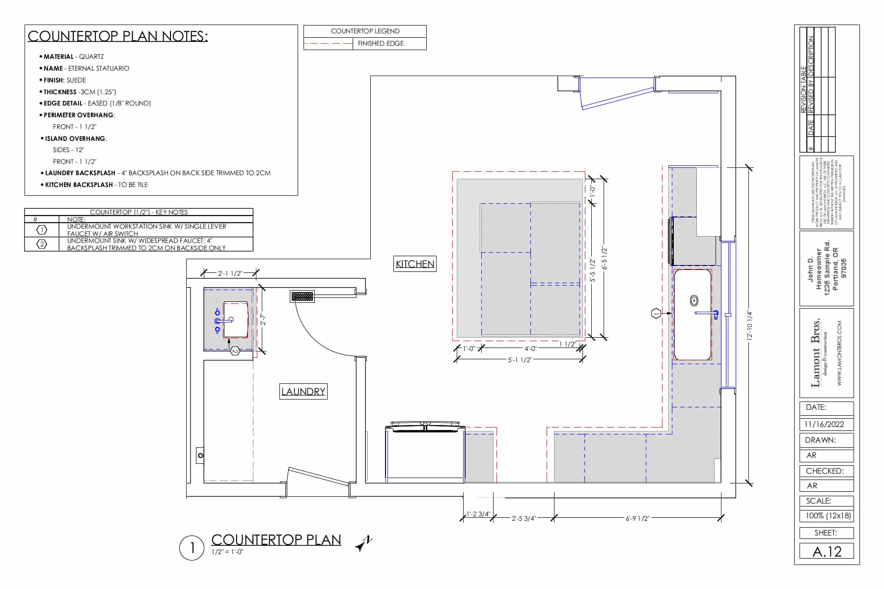
Cabinet drawings may include both plans and elevations. Cabinet codes connect each box to a schedule listing its type, dimensions, doors, drawers, accessories, and modifications.
Pay close attention to the cabinets used for trash, pantry storage, appliances, and corners. These details affect daily use more than the cabinet color alone.
Electrical, Lighting, Plumbing, and Mechanical Plans
Technical sheets are primarily used by licensed trades, but homeowners should review the parts that affect daily use.
Electrical and Lighting
The electrical plan may show outlets, switches, light fixtures, smoke alarms, appliance connections, and dedicated circuits.
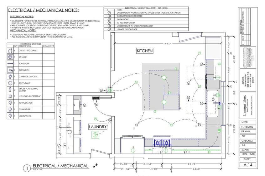
Check outlet placement around desks, islands, vanities, and small appliances. Trace which switches control which lights. Confirm fixture locations in relation to cabinets, mirrors, furniture, and walkways.
A light centered in the room may not be centered over a table or island. The drawing should reflect how the room will actually be arranged.
Plumbing
Plumbing drawings locate fixtures, supply lines, drains, and venting. The level of detail varies by project.
Homeowners should confirm the locations of sinks, toilets, showers, tubs, faucets, floor drains, and other visible fixtures. The plumbing team remains responsible for technical sizing and code requirements.
Mechanical
Mechanical plans may show heating, cooling, ventilation, ductwork, registers, exhaust fans, and equipment locations.
Review the placement of visible registers, thermostats, fans, and exterior vents. These components need to perform correctly without conflicting with cabinetry, lighting, or the design of the room.
How to Read Revisions
Construction drawings can change during design, permitting, and construction.
A revision block records when a sheet changed and may briefly describe the update. Revision clouds or similar marks can identify the area that was modified.
When you receive a revised set, review the revision record first. Then locate each changed area and compare it with the previous version if needed.
Keep questions and approvals in writing. A clear record helps the designer, project manager, purchasing team, and field team work from the same decision.
If a change occurs after the construction contract is signed, it may require a formal change order. Our guide to remodeling change orders explains how those updates affect plans, pricing, purchasing, and construction.
What Should a Homeowner Check Before Approving the Plans?
You are not expected to verify engineering calculations or code compliance. Focus on the decisions that affect how you will use and experience the home.
Review room layouts, doors, windows, cabinetry, appliance locations, plumbing fixtures, lighting, switches, outlets, storage, and finish selections. Look at floor plans and elevations together. A fixture that appears correctly placed from above may look too high, too low, or poorly aligned in elevation.
Move through a typical day in your mind. Picture opening the refrigerator, unloading the dishwasher, entering the shower, storing towels, charging devices, and turning lights on as you enter a room.
Ask questions when something is unclear. Construction drawings are professional documents, but they should still communicate the design well enough for you to make informed approvals.
What If Two Drawings Conflict?
Do not resolve a drawing conflict by guessing.
A floor plan, elevation, schedule, specification, or detail may contain information that appears inconsistent. Send the question to the designer or project manager and identify the sheet numbers and locations involved.
The team can issue a written clarification or revised drawing. This keeps the design record current and prevents separate trades from making different assumptions.
The purpose of a coordinated plan set is to give everyone one source of direction. When that direction is unclear, the right response is clarification before installation.
Frequently Asked Questions
Where should I start when reading construction blueprints?
Begin with the sheet index and title block. Confirm the project, sheet title, scale, date, and revision. Then read the legend and general notes before moving into the drawings.
Should I read the floor plan first?
Review the existing, demolition, and proposed floor plans early, but do not stop there. Follow references to the elevations, sections, details, and schedules that explain the design more fully.
Can I measure dimensions directly from a blueprint?
Use written dimensions whenever possible. Printed and digital drawings may be resized, which can make physical measurements inaccurate.
What do dashed lines mean on construction drawings?
Dashed lines can represent hidden, overhead, existing, or demolished elements. Their meaning depends on the drawing and legend.
What is the difference between a floor plan and an elevation?
A floor plan looks down on the horizontal layout. An elevation looks directly at one vertical wall or side of the building.
What is the difference between an elevation and a section?
An elevation shows a surface from one side. A section cuts through the building to reveal concealed construction and vertical relationships.
What should I do if I do not recognize a symbol?
Check the legend, abbreviations, and general notes. If the symbol is not defined or remains unclear, ask the designer or project manager.
Are permit plans and construction plans the same?
They often overlap, but the final construction set may include added information for pricing, purchasing, fabrication, or installation. Confirm which approved set the project team is using in the field.
Construction Drawings Protect the Design
Construction drawings are more than a permit requirement. They record the decisions that shape the finished home and give the construction team a consistent source of direction.
At Lamont Bros. Design & Construction, our designers and builders work together as those documents develop. Construction input helps the design account for existing conditions, materials, budget, and installation. During the build, the drawings help protect the decisions made with the homeowner rather than leaving each trade to interpret the project independently.
Download our Six Step Remodeling Guide to see how drawings fit into the full design-build process, or schedule a conversation with our team when you are ready to begin planning your remodel.
-1.jpg)